I recently completed a DIY solar project at my residence, becoming the first in my city to do the entire design, engineering and installation myself. Based on the research I did throughout the process, and the reactions and questions from the engineers I used, I also wager I’m one of the only in the country to do it all.
Why would I DIY my solar system you might ask? Cost and ROI, plain and simple.
Basics
The first step is deciding what kind of system to put in, DC or AC. Each have their advantages, and I’ll talk about each.
DC System
I’m not super familiar with all of the options with a DC system, as this is not the system type I chose. However, the basic idea is that all panels generate power in DC, and you store power as DC in a battery. So the panels connect directly to a solar charge controller and battery system, which in turn has an inverter to power devices in your home from the battery.
It is more efficient to charge the battery directly via DC, but the cost of this type of system is substantial.
AC System
An AC system is really quite simple. Each panel or pair of panels connects to an inverter. The inverter converts the DC power from the panel to AC and synchronizes with the grid. Ultra-simplified, the wires coming down from the roof flow to the breaker panel and power things in your home or go backwards out to the grid for a credit from your energy company.
There is no battery involved, so the general components of the system are not very expensive. And if you know AC wiring basics from around the home, there’s nothing that much different in the installation.
I chose an AC system because of the cost of the battery systems, allowing me to choose in the future if I want to add a battery to my setup, but keeping initial costs manageable. Also, each inverter works independently, so when some panels are shaded, broken or covered with snow, there is no impact to other panels.
Getting Started
I happened into this project somewhat by chance. A friend of mine had recently installed his own solar panels on his home, and I was intrigued by what he had done.
For his project, he utilized a DIY contractor to design, engineer, package and ship him everything he needed for his installation, including all the install instructions and steps, greatly simplifying the work needed to accomplish the end result.
By the time I took on this project, the overhead and engineering costs for the same DIY contractor were substantial, much more than what he had originally paid. I also didn’t love the proposal they sent me, the types of equipment and sizes they selected, and I thought I could do better on my own.
My friend was kind enough to share his interconnection agreement documents he submitted to the city as a template for me to use in designing my own, and I took it from there.
Design
I spent many months researching different types of panels, inverters, sizes, types, and connectivity options. Even in my “final” plans submitted to the city in my interconnection agreement, my plans weren’t finished. I continued to learn as I went, communicate with the city and the inspector, and improved my designs throughout. The electrical inspector may have considered that a hassle, was probably annoyed with me from time-to-time, but he was very kind and also very interested in what I was doing and how cost-effective it was.
I used several simple tools in order to design and build out my system, and to create the necessary BOMs for equipment to order:
- My friend’s original interconnection agreement + Adobe Acrobat to edit it and make changes, resulting in my interconnection agreement.
- Communications with the city electrical inspector enabled me to understand restrictions such as the fire setbacks from the peak and side of the roof, rules such as the 125% panel bus rule, breaker certification, etc.
- Open Solar – a free panel layout and design tool that helped me understand how many panels I could fit on my roof, and it what layout.
- I plugged in my address, and from there it pulled up a satellite view of my home and knew my roof dimensions and layout
- I could place the panels directly on my roof to see how various sizes of panels fit, and what orientation made the best use of space
- My process was slightly more complex than most because I had recently done a garage addition, so the satellite photo Open Solar had was outdated and did not reflect my entire roof. This required me overlaying a drone photo and following precise directions to orient and scale the photo properly so it still knew my roof dimensions.
- Snap-N-Rack Design Tool – a free rack layout tool that helped me build the full BOM of components I needed to order for the rack system
- The rack component were quite a bit more complex to determine than the solar supplies, so this tool was very important.
- Even using the tool, I still messed up and was a few parts short for certain components, which is where small orders from Signature Solar were helpful.
- Communications with Aptos customer support to answer questions and to receive some helpful guidance on how wiring between each panel/inverter works.
- Aptos also advised me on some additional components I needed to make sure that I order, including specifics on the Trunk cable lengths, end caps, a few of the needed tools, and the DTU.
- You can review everything that I ordered and what it was for in my Equipment section.
Permitting
There were several things I needed to put together before starting on the project. My city required the following:
- Electrical Permit
- Building Permit – to assess and approve support for the panel’s weight on the roof
- Interconnection Agreement – the agreement allowing me to connect into the electrical grid
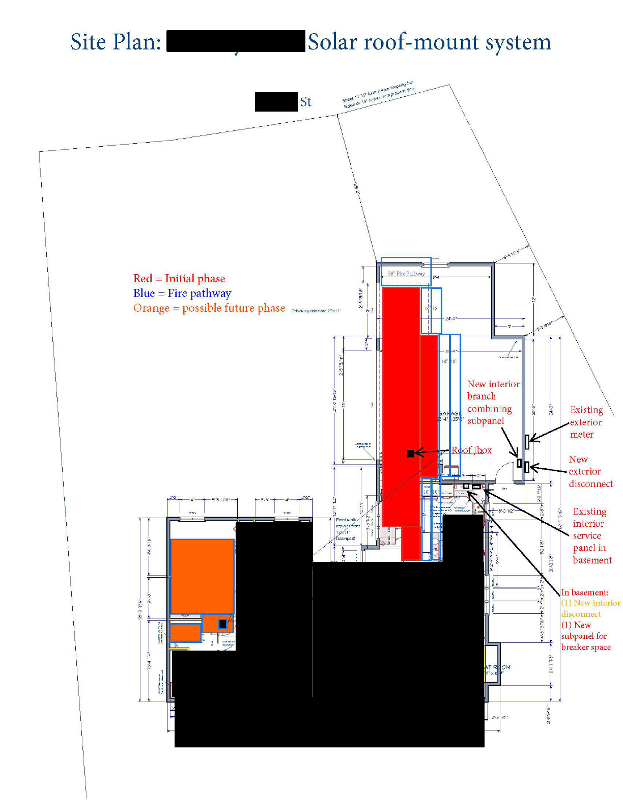
For all of the above, having a full picture of what I wanted to do in the beginning made a big difference. The interconnection agreement is specific to the size of the array, so it made the work of myself and the city much simpler knowing the full phase 1 & 2 scope of the project from the beginning. The city was able to review and approve the entire scope of the project initially, which saved us all time in not needing to repeat the process when it was time for me to install my phase 2 panels.
Additionally, because I had shared my full plans with the electrical inspector, he confirmed that my plans would indeed support the larger system outlined in phase 2 from the beginning, and he was able to leave my permits open after phase 1, which prevented me from having to pay for a second set of permits when I installed phase 2.
Getting Certified Plans
In talking to the city, they also made it clear that my electrical one-line diagram and the structural diagram for the roof needed to be certified by Iowa licensed engineers. I am neither a certified electrical engineer nor a certified structural engineer. I called some local and regional engineering shops and was quoted quite astronomical amounts of money for this review and certification. Hard pass, this is where I got a bit creative.
There had to be a trick, so I looked again at the plans my friend had shared. Each of those two pages, the electrical and structural pages, were stamped by a licensed engineer. It took a bit of creative Googling of the license numbers, but I finally located the firms for the two engineers. They are referenced in my helpful contacts section.
Reaching out to each, I was able to get them all of the information they needed, and their certifications of my documents were very economical.
Getting Things up to Code
Through my discussions with the city, it also became obvious that I needed to rectify some past missteps of my own in my past DIY electrical projects. I learned that each panel that exists has a specific breaker brand and type that is certified for use with it, even if that panel manufacturer is no longer in business. Previously, I had just bought breakers that fit the panel, but didn’t pay attention to the brand. Additionally, to squeeze a few extra circuits into my house, I had replaced several breakers with single-pole double-breakers that weren’t certified for my older panel.
So the very first thing I needed to do was to install an electrical subpanel, and peel quite a few circuits off my main panel, allowing me to replace those non-certified breakers with certified ones again. This, in itself, was quite a project, but now has me in a pretty good place, including if I ever choose to install batteries into my system. I’ll talk about that later.




Inside Electrical Work
Before jumping up on the roof, there are quite a few steps that needed to be completed:
- The 6awg wire run
- The outdoor disconnect
- The indoor branch combiner panel
Six Gauge Wire Run
 I chose 6awg because I wanted to support the potential future phase 2 circuit as well, so I initially installed everything to support the full system. This required me sizing up the cable to 6awg in the event I decided to add the third phase 2 circuit.
The wire ran from the basement subpanel to the outdoor disconnect, through the branch combiner panel. I ran the wire in the metal clad casing so I didn’t also have to run conduit to protect the wires.
The wire ran to the branch combiner panel first, even though they didn’t stop there. Once in the branch combiner panel and before cutting them to length, I removed the metal clad casing once the wire was inside the panel. I then split the red and black wires from the others and fed those to back out of the branch combiner panel, through the PVC to the outdoor disconnect. I mounted the outdoor disconnect directly opposite the branch combiner panel on the other side of the garage wall, allowing a simple, straight and short PVC run between the two. The white ran directly to the neutral bar lug of the combiner panel, and the ground to the ground bar of the panel. I ran a second ground wire from the combiner panel ground bar through the same PVC to the outdoor disconnect ground bar.
Outdoor Disconnect
The Outdoor Disconnect is mounted on the outside of the house, accessible by utility workers in the event they need to shut off the power from the panels.
I mounted the disconnect directly opposite the branch combiner panel inside the garage, allowing a simple and short PVC run to connect them. This allowed me to run the wires directly with no casing.
The black and red wires run from downstairs, through the branch combiner panel, back out through the PVC to the outdoor disconnect, and connect to the lugs on one side of the disconnect switch. A second set of red and black wires connect to the lugs on the other side of the disconnect switch, then run back through the PVC to the branch combiner panel’s main lugs, and complete the circuit.
Indoor Branch Combiner Panel
The indoor branch combiner panel serves as the panel to combine the multiple circuits from the panels on the roof into one circuit that runs through the outdoor disconnect and downstairs to connect into the home’s electrical system.
This panel is a main lug panel, in other words it doesn’t have a main breaker, just lugs to connect the wires directly to the panel bus. Each circuit from the panels connects to the bus through an individual 2-pole 20amp breaker.
Each circuit from the panels arrives in the branch combiner panel in a 12/3+ground or 10/3+ground wire. The white isn’t used, so technically these wires probably could be 12/2+ground or 10/2+ground wires. The red and black connect to the two different lugs on the 2-pole 20amp breaker, and the ground to the ground bar. I went ahead and connected the white to the neutral bar, even though it isn’t used.
I purchased a larger-than-needed branch combiner panel (8 circuits) which allowed me the opportunity to add the 3rd solar circuit during my phase 2 project, each solar circuit consuming 2 circuits of the panel as they are each 2-pole circuits.
Site Placard and Stickers
Electrical code requires special labeling on the solar circuits, as well as outside on the outdoor disconnect and electric meter. You will notice a few of them in some of my pictures, though I applied all of the stickers at the end, so some earlier pictures may not have all of the stickers applied yet. I purchased a generic PV Labels sheet that included everything I needed, except for the Site Placard (shown on the right), which I just created myself and had printed at my local Staples. Specific labels you need:
- Site Placard (on the meter)
- Caution solar electric system connected (on the meter)
- Dual power supply (on the meter)
- Outdoor disconnect for solar system (on the outdoor disconnect)
- Solar system voltage/amperage (on the outdoor disconnect)
- PV circuits only (inside branch combiner panel)
- Caution solar circuit (outside branch combiner panel)
- Multiple sources of power (outside main & subpanel)
- Solar circuit (for the solar shut-off in your main / subpanel)
Overview Video
The final image on the right is getting a little ahead of ourselves, but it talks about how the panels from the roof are wired all the way down to the panel in the basement. It starts at the rooftop junction box, and talks through the branch combiner panel, to the outdoor disconnect, and then from there to be basement.


Rack Installation
The very first step up on the roof is figuring out the placement for the rack. The rack is actually very simple, there’s several key components all outlined in the Equipment section:
- The rail itself, everything easily clips into the rail
- End and mid-clamps which clip into the rail and clamp down on either the outside end of a panel, or between two panels
- Omni-lugs which are used to attach the inverters to the rail, and the ground wire to the rail
- Rail feet that attach the rail itself to the roof flashing
- Roof flashing that affix the feet to the roof and allow the one bolt through the roof without causing a leak
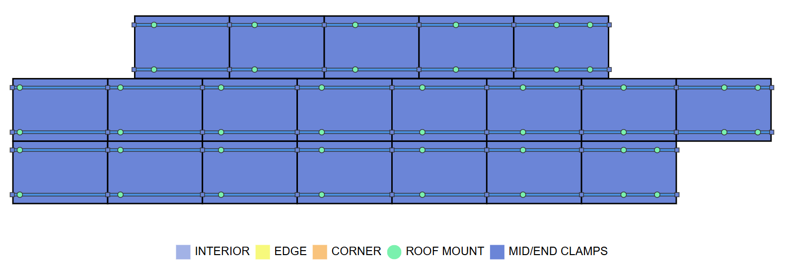
With this design, it means that the rail must always extend about an inch past the outside of the last panel on each end, and it means that there’s about an inch between each panel (for the mid-clamp) along the run of the rail. Panels can touch each other in the perpendicular direction to the rail, but are spaced apart along the rail.
Sometimes your trusses don’t line up exactly where you want to begin the rail, so you are allowed a moderate amount of cantilever past the last foot. I believe the maximum for my region and snow load would allow for 18″ of cantilever, but I tried not to ever exceed 12″. In certain cases where it was going to be a larger cantilever, I just added one additional foot and extended the rail past the end of the panel.
Locating Your Trusses
Starting out, you have to locate your trusses and determine if there are any sections within your roof where the trusses do not follow the standard 24″ on center layout. This can happen in places where different pitches of the roof meet or where other architectural things are going on with the roof.
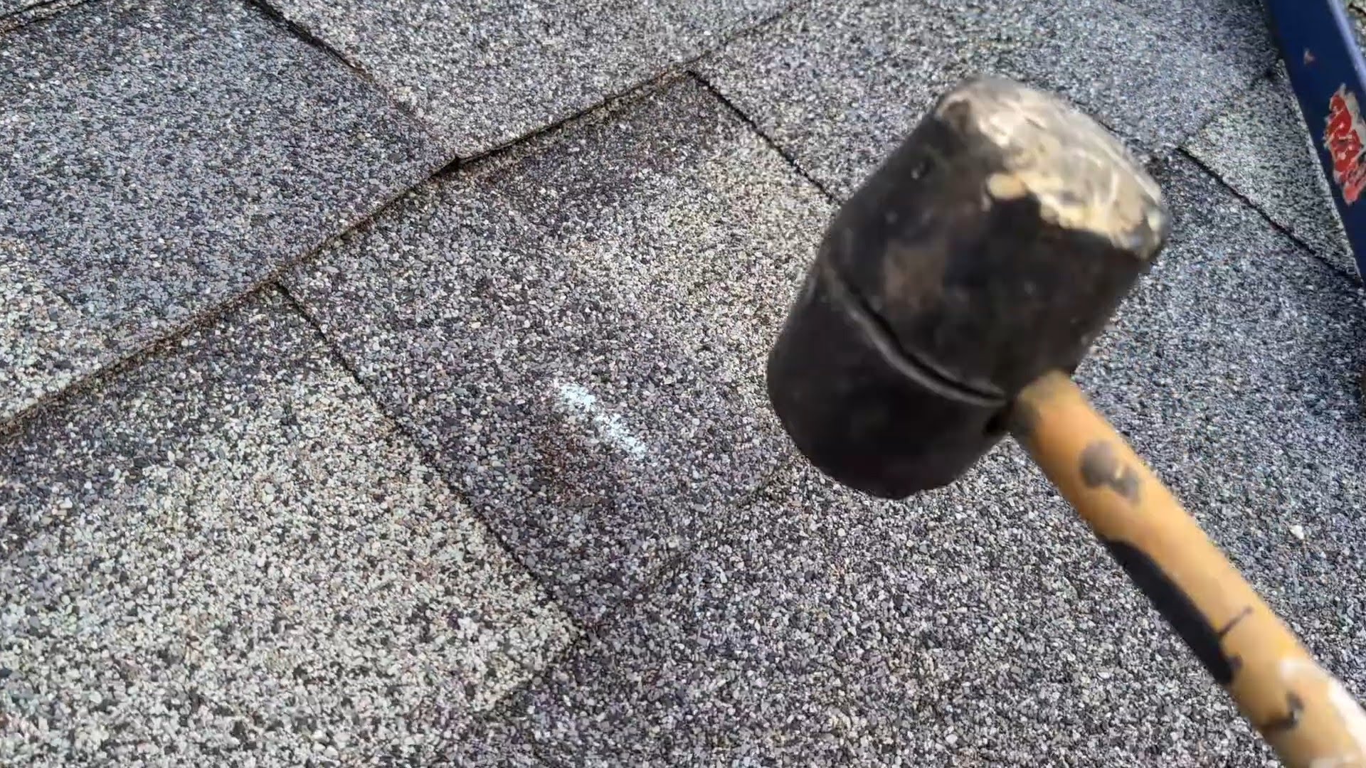
I started in the attic and followed the trusses all the way to the far end of the roof where I was starting. At that end, the soffit and some changes in width of my garage caused some areas where the trusses weren’t all 24″ on center. I used some small doorbell wire to mark key places where the trusses differed, and where standard sections began/ended. I used the ridge vent of my roof, and carefully slid the wire out to where I could see them from the roof side at all of these places. I used a rubber mallet to verify the locations of trusses that I marked and measured from those marks.
From there, I could mark with sidewalk chalk and chalk line the location of all of the trusses across the roof. I measured my firefighter setbacks from the side and peak of the roof (36″ from the side, 18″ from the peak), and sketched out the boundary of my panels on the roof with sidewalk chalk. This gave us the space to begin mounting the rail.
With the area defined, I now began planning out the rail placement and feet locations. The Snap-N-Rack design tool recommended 72″ separations for the feet along the rail, or every third truss for standardly spaced trusses. My garage solar rack worked out nicely where the first foot was right at the 36″ mark. I planned for about 6″ of overhang on the bottom side of the panel, and 6″ of overhang on the top side of the panel, which gave me rails spaced about 30″ apart for the bottom row of panels.
The second row of panels started about 12″ above the first row, resulting in one rail starting about 24″ from the gutter, then 30″ to the next, 12″ to the next, 30″ and so on. This gave me a clearance below my panels of 18″, which allowed me to fit within the firefighter setbacks but still be able to walk below my panels and the edge of the roof comfortably.
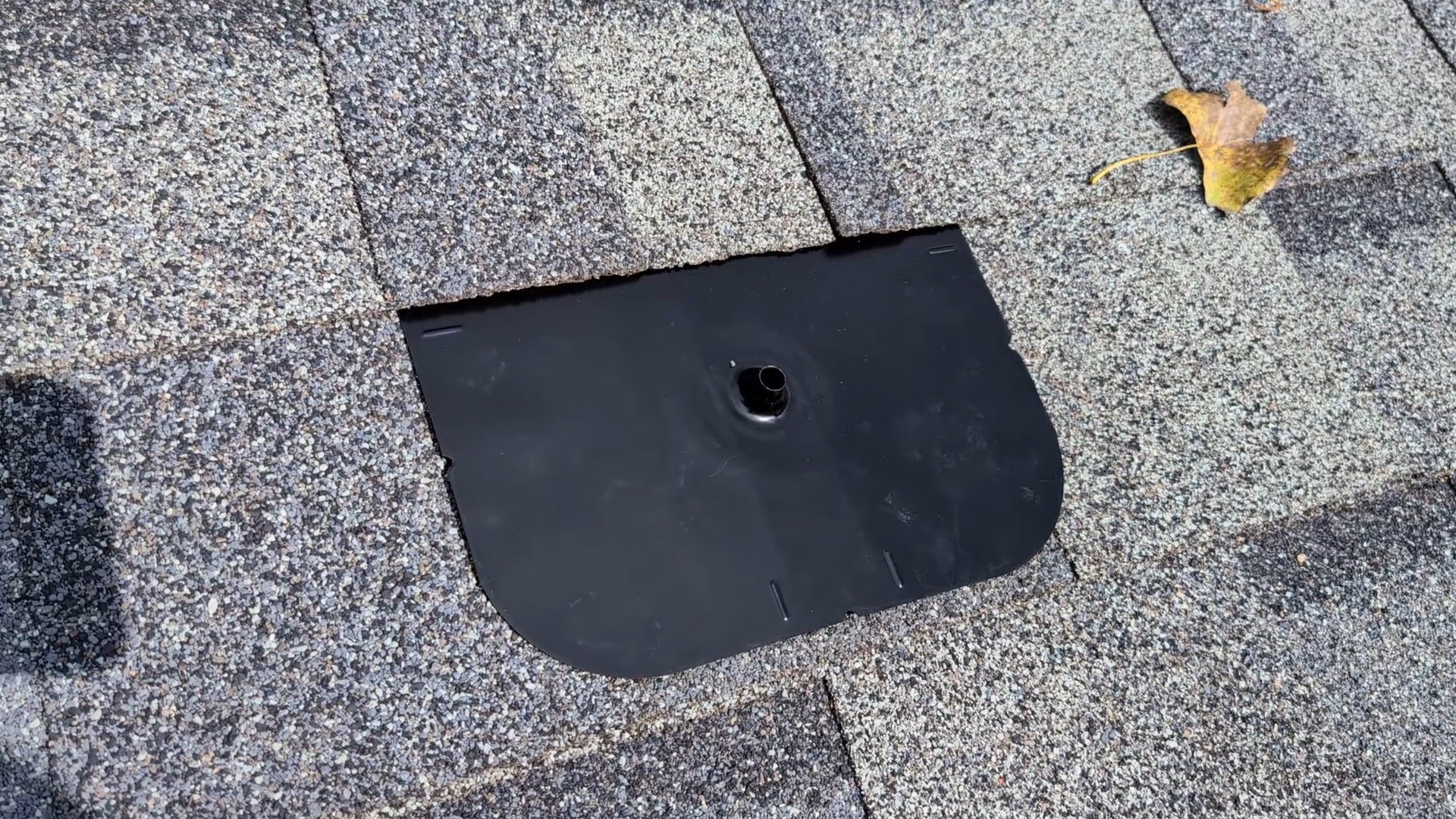
Loosening the Shingle for the Flashing
Of the whole project, this is the part I hated the most – putting holes in my roof. The Snap-N-Rack’s design does help, however. I discovered very quickly that the best time to do this work is when it’s sunny, this helps soften the tar between the layers of shingles and enables you to fairly easily separate the top layer with the flat bar. I wouldn’t try doing this on a cold or cloudy day unless you really know what you are doing.
Once you’ve identified where your foot is going to go, follow the steps that are outlined in the first video on the right: Loosening the shingles and placing the flashing. I used a flat bar, and very carefully wiggled it back and forth until I was able to get through the ~2″ of the bottom edge of the shingle where the tar is applied. Be careful *not* to twist or pry, as this action can easily rip the shingle. Also, don’t hammer the flat bar in, this can easily rip or tear either the shingle you’re separating or the shingle below. The warmth from the sun makes this pretty easy, by just wiggling back and forth. Once you get through the tar section once, then just work on each of the separated edges to widen.
Drilling the Hole to Mount the Foot
Once the shingle is loosened enough to slide the flashing in, you line the nipple of the flashing up with the mark for your truss, and then we’re ready to drill our pilot hole. Before drilling, it’s probably good to double-check the truss location again with a rubber mallet, I did have a couple of cases where my chalk lines got off a bit from the top of the roof to the bottom, so check twice and drill once. I used a 1/8″ drill bit, leaving plenty of wood remaining for the 5/8″ umbrella lag to grab.
With the roof marked by the pilot hole, you can pull the flashing out and drill the full hole. If you hit the truss, it will feel solid for the entire depth. If it slips through with no resistance, you missed the truss. In this case, double-check the location of the truss and re-drill. You can use a Rafter Center-line Locator tool to confirm which side of the truss your hole missed on, or the rubber mallet again. In the couple of cases I did this, I also filled the incorrect hole with the roof sealant, though the miss was still under the flashing and within the sealant U, so this probably wasn’t necessary.
Mounting the Flashing and Foot
Verify your flashing still fits properly and you can line the flashing up with your hole. Widen your opening between the shingles if needed.
Then, as shown in the Attaching the rack foot to the roof video, we need to apply some sealant to the flashing, in an upside-down U shape. I used APOC 501 Elastomeric Roof Sealant. Carefully slide the flashing back up under the shingle and line the nipple up with your hole, trying to minimize the amount you drag the sealant across the shingle below.
Next, peel the white plastic protector from the bottom of your Anchorfoot and place one of the two large holes over the nipple in the flashing. Be sure to orient it correctly so they are all facing the same direction, and ensure it is level. Once you place it, the tar is very sticky and it doesn’t want to come back off.
Use the umbrella lag to fasten the Anchorfoot to the truss. If successful, the lag will suck the Anchorfoot down and squish out the tar a bit. If that happens, stop tightening, the foot is secure. If it doesn’t suck down, it could be that the truss split out or you missed the truss, you’ll need to pull everything apart and find a different spot to drill the hole. In the one case this happened to me, I needed to switch to a different truss to find one that held. In doing so, I covered up the mess and multiple holes from the prior spot with a piece of stainless flashing that I put in place of where the Snap-N-Rack flashing would have been.
Panel Installation
I started the panel installation by ensuring my layout, microinverter locations and cabling all worked. I referenced the original suggestions provided by APTOS:

Using this initial concept, I was able to lay things out and confirmed that the trunk cable would reach each location. I then started to mount the inverters.
Here’s the important part, I originally didn’t realize that I needed to capture the location of each microinverter. But once I began setting up the DTU, discussed more in the Monitoring section, I needed the exact location of each microinverter, and had to go back, pull up the installed panels, and get the micro identification number for each micro.
Each micro has two labels on it with the identifying number, one that can’t be removed, and another that can be peeled off. I printed off a copy of my layout and put the peeled stickers on that layout at each location for each microinverter:

This gave me a reference later, in the Aptos Installer app, to lay out the inverters and the panels. The second time I did this, I was careful to mark which side of the inverter I connected which panel to as well, that way I know exactly what each panel is producing. This is helpful in the winter with snow, and in the event of damage or some other anomaly, I’ll be able to pinpoint the problematic panels fairly easily.
Laying Out the Micros
Keep in mind, while the branch combiner panel is hooked up at this time, the 20A breakers for each circuit have not been turned on. Therefore, all the wiring up to the roof is inactive. Additionally, without power from the grid, the microinverter will not activate, so no power will be generated by the inverter. As far as the panel is concerned, connecting the PV cables to the micro is no big deal, sun or no sun. So during all of these steps, you don’t need to worry about electricity.
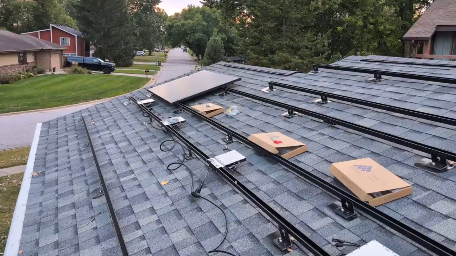
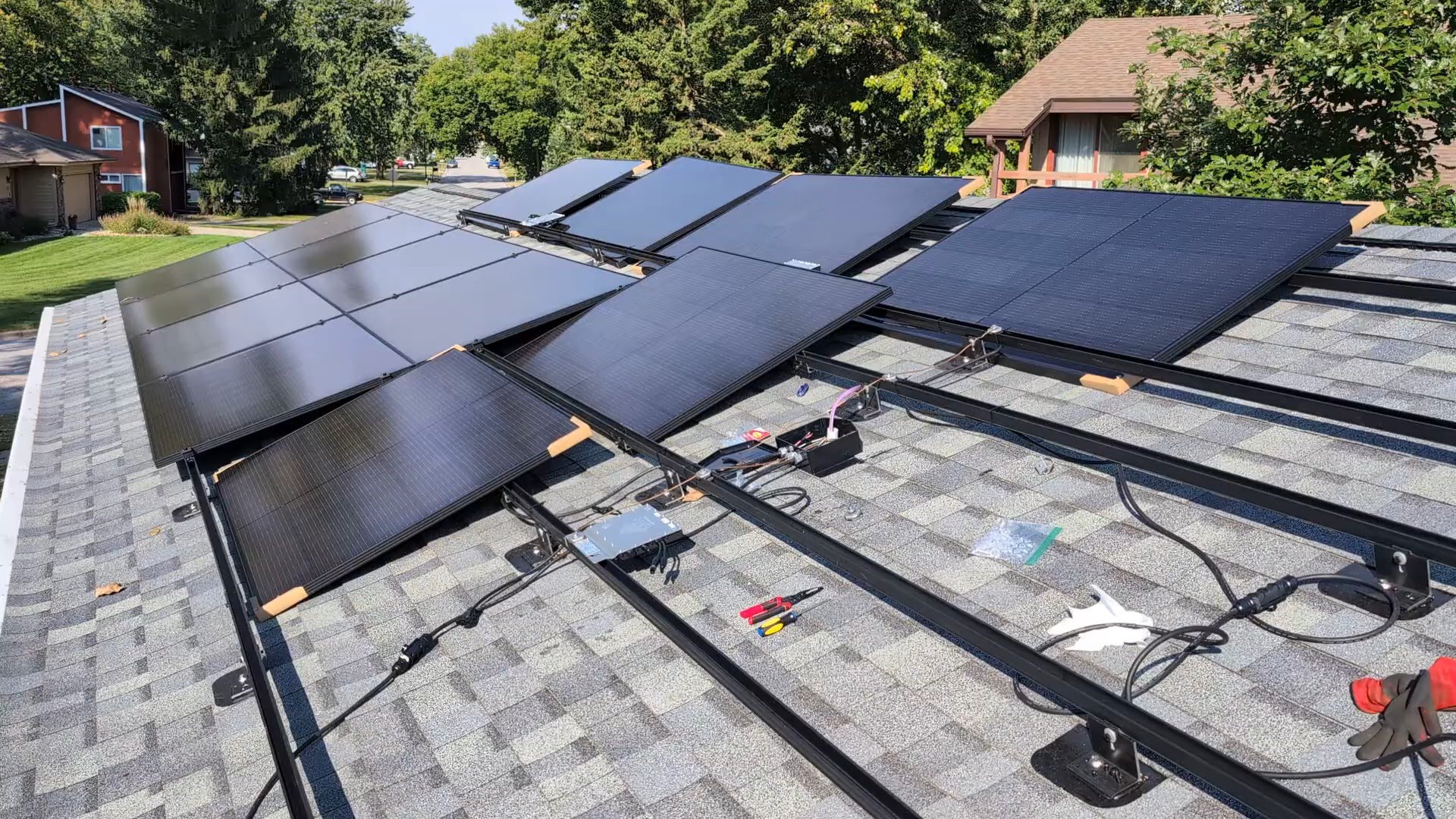
As the videos on the right illustrate, the first step is to lay out the micros, get them mounted, plug them in, and secure the cabling. Electrical code requires that all cables be secure and do not have contact with the roof. This is to prevent wear over time from short-circuiting the wires. So large and small sized cable ties are a necessity for the installation, using the large ones to secure the trunk cable to the rail, and the smaller ones for the PV cables from the panels.
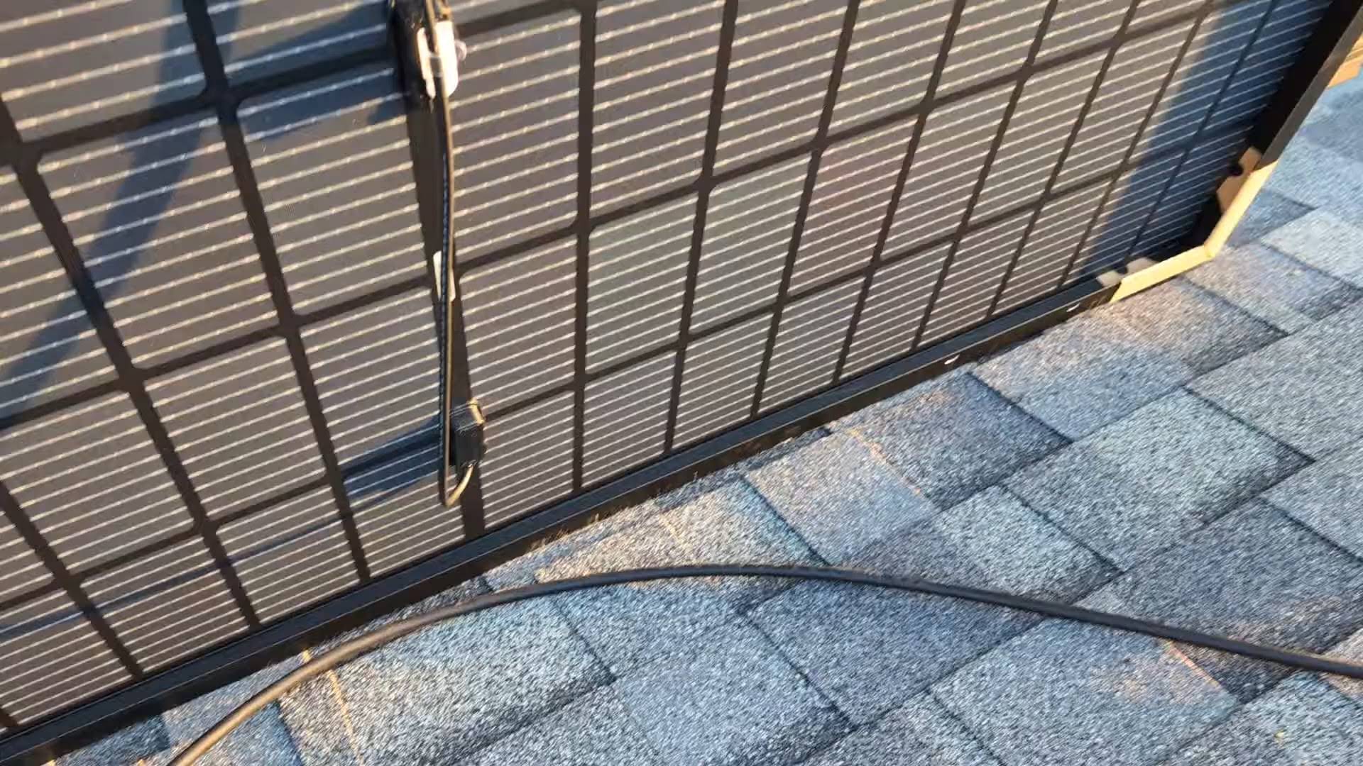
For my first two rows, the layout was pretty easy. The micro was placed in the middle of the panel half-way covered by the bottom panel and half-way covered by the upper panel. In this situation, the PV cables coming from each side of the panels themselves are long enough as-is to reach the micro, and no PV extensions were needed. As shown in the videos, I left the close-side PV wire of the panels zip-tied as they came from the manufacturer. This kept those cables managed, and there was still enough play in it to plug it into the micro. The far one I cut the manufacturer zip-ties and zip-tied the wire to the close PV cable to create tension, keeping the wire suspended. I also used a command-strip hook in the middle of the panel to ensure it stays up off the roof, this probably wasn’t necessary.
The third row was a bit trickier, because the panels were wired end-to-end rather than top-to-bottom. I had to clip all of the manufacturer provided zip-ties on the panel PV cables, and secure each side to one of the holes in the end of the panel. This was done again to provide tension on that PV cable so it doesn’t droop down. There was still just enough PV cable to connect into the micro, even though the micro had to be offset to the side of one panel rather than perfectly centered due to the mid-clamp needing to be attached to the rail where the panels meet. It all still fit fine, but was a bit trickier to get all the cabling properly managed in this orientation.
Finally, the third row also connected up to those panels on the far right that were wired to each other on a diagonal. In these cases, the micro was still mounted under one of the two panels in the closest corner to the other panel, and the other panel required one or two small 3′ PV extension cables to reach the micro. Also not a big deal, just a bit more wire management.
Placing the Panels
In my phase 1 project, I used smaller panels sized almost exactly to the micros. I realized later that this was a bad plan. Oversizing the panel allows it to produce more power at all times, and only clips (produces more power than the micro can convert) during a short window of peak sun each day. This fact is exacerbated by my roof’s pitch. Being 4/12, my roof is not terribly steep. So much so that the panels never reach their peak generation ability, they would generate more if they were at a larger pitch. So oversizing the panels naturally allows them to come closer to the peak output of the micro.
My wife and daughters would pass a few panels up to me at a time from the ground, and I laid them on one rail propped against another to keep them from sliding off the roof. I then started with the bottom row, as once those panels are in place, the remaining ones above them are much easier to place. I attached the end/mid clamps to the rail, then placed the panel in it’s place. I temporarily secured the panel loosely with the bottom two clamps, enough so the panel wouldn’t slide but would let me lift the panel to access and situate the wires. Once things were set, I then arranged the panel to level and fully clamped it down with all 4 clamps.
Mounting the jBox
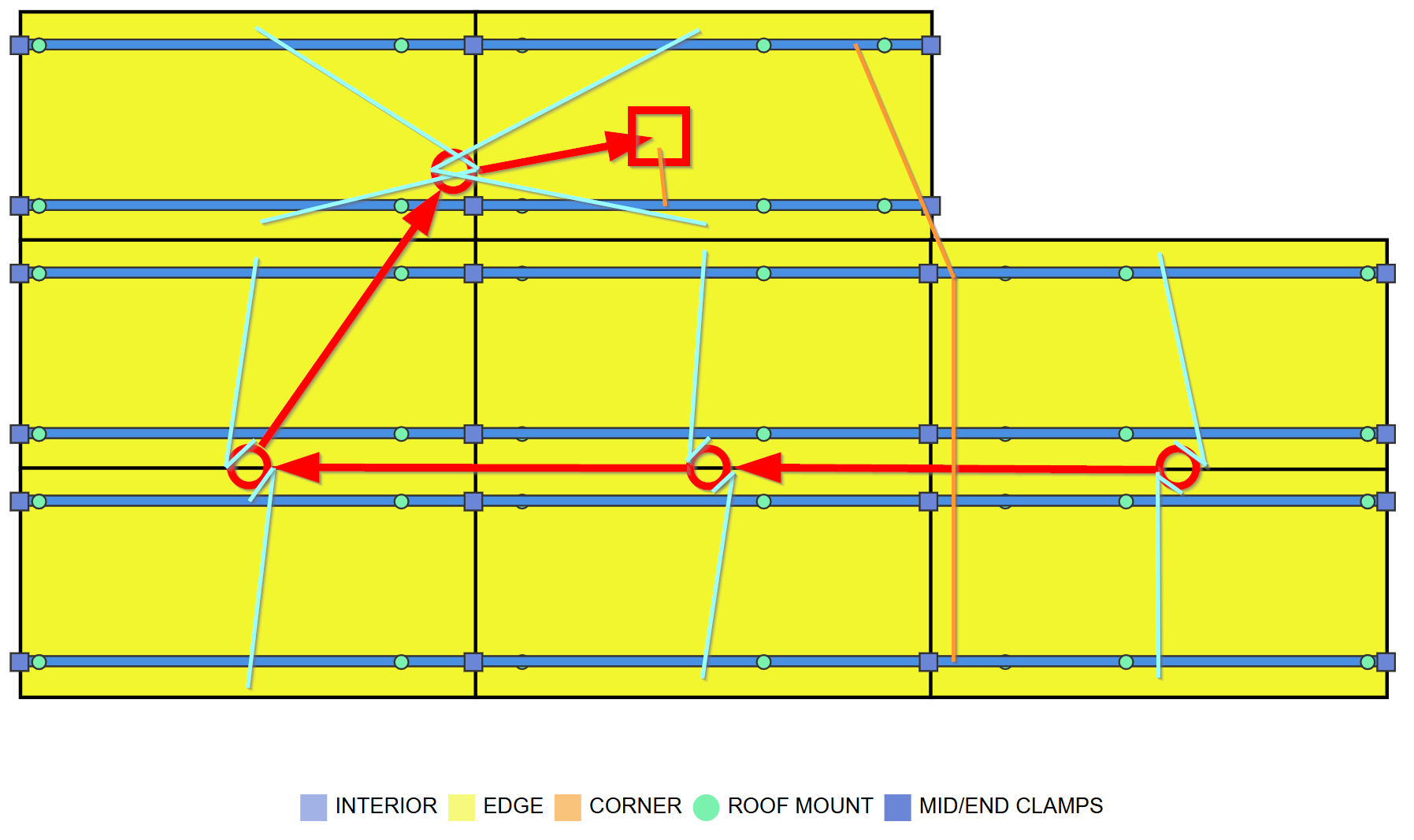
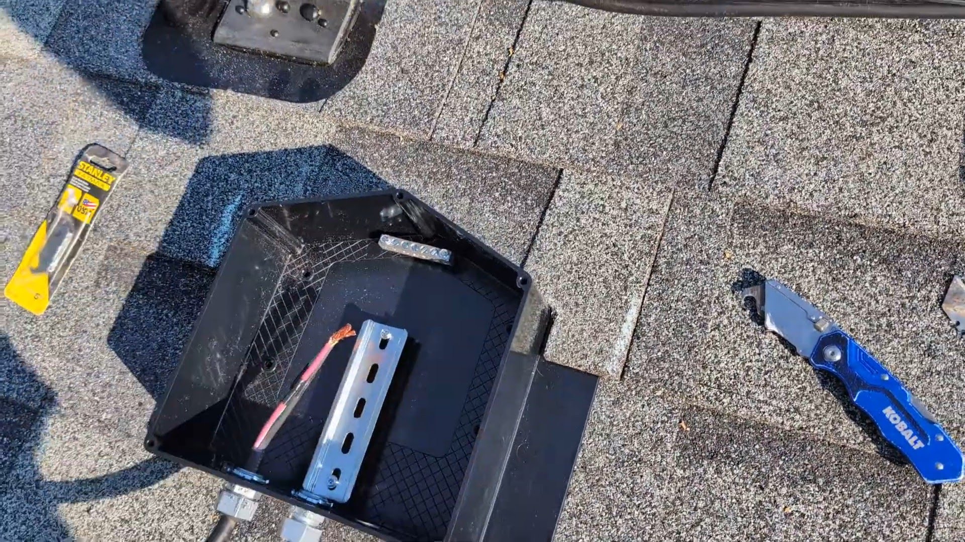
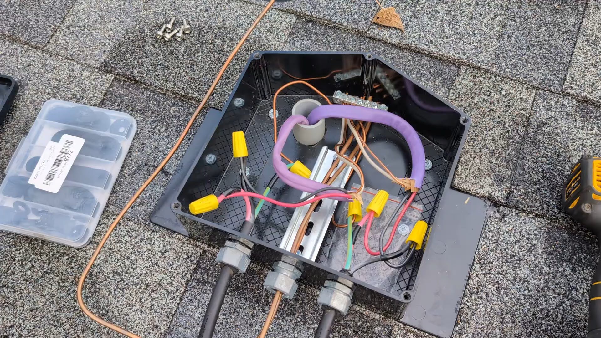
The roof-top junction box (jbox) is the exterior location where all of the trunk cables come together and join together with the inside wiring coming up through the attic. This should be placed at the point where all of the trunk cables can come together the easiest. You can see the point in the picture above for my garage array where the yellow and pink lines meet. This is where I installed my jbox. The jbox is thin enough that it fits nicely under the panels, so all you have to avoid is a location where there’s a truss in the way under the roof, and avoid the rails and micros.
The jbox has a flashing that gets installed under a layer of the shingles, similar to the rail foot flashing. As the video shows, on a sunny day you carefully pry up the layer of shingles. Use only back-and-forth movements with the flat bar, don’t twist or pound it. As the video shows, slide the box up under the shingle, then mark a line to cut out the shingle in the shape of the box’s pointy top. Use a roofing blade in your utility knife to cut the shape out of just the top level shingle, and slide the box up to make sure you have a nice fit. The goal here is to have about 6″ or more of the flashing up under the shingle.
Similar to the foot flashings, once you’re ready to mount it, put a U-shaped bead of roof sealant on the jbox (being sure to stay outside of the pre-drilled holes in the jbox for mounting or wiring), then slide it up under the shingles with as little friction on the sealant as possible so it doesn’t smear too thin. Use the Mounting holes to put a couple of screws into the sheeting to mount the box. Then drill a hole down through the jbox, shingles and plywood into your attic. I believe I used a 1″ bit to drill this hole, enough to fit the PVC through easily but prevents the larger top connector of the PVC from sliding through. I then pushed the wire through the PVC and into the jbox, leaving plenty of extra inside the jbox to easily wire, but not crowd things up too much. After connecting all the wires and settling things, I put some sealant around the PVC where it goes through the hole, mostly just to hold the PVC in place.
Wiring the Trunk Cable
Connecting the trunk cable to the inverters is literally a snap. There’s only one direction it will fit, and it clicks in with a nice solid click. You need the trunk cable disconnect tool if you want to take this off, it’s cheap so I would buy one. At the far end of your trunk cable, you install the cap at the last connector. On the jbox end, the wire comes stripped with ~3″ of individual colored wires exposed.
The trunk cable enters the jbox on the downward side. I drilled 3 holes in the downward side of the jbox, one for each solar circuit and a 3rd for the ground wires. I used waterproof gaskets in each of the holes, which were a huge pain and probably overkill that wasn’t really necessary due to the design of the jbox, you probably could get away with a standard grommet. Each trunk cable is it’s own circuit, and should be wired to it’s own NM/B 12/3+ground or 10/3+ground wire. Wiring is simple, black-to-black, red-to-red, ground-to-ground. White from the NM/B wire isn’t used, but can be tied into the ground bar in the jbox and to the neutral bar of the combiner panel.
Monitoring the System
One of my favorite things to do now is to monitor the system. With my power company, the agreement I get for generated electricity surplus is a 60% credit (wholesale rate) on my bill. What this basically means is if I’m generating a surplus (more electricity than I’m using), the meter counts that separately going back out. At the end of the month, I get a bill for the electricity that I consumed from the grid, and I get a credit for the electricity I generated and sent back to the grid. But it also means that if I generate a surplus one minute, then start the dryer and buy it back the next, I sold it for $0.60 and bought it back for $1.00.
While this is not enough for me to consider adding batteries to my system (at least yet), it does annoy me. So I’ve gamified the system and try to work it so that I heat the hot tub with the sun, I run the laundry, cook, charge the car and run the dishes all at times when I’m generating power. I’m not winning this game, because we end up charging the car at 4:30 after the peak sun, but it does make a difference.
Equipment
There are two pieces of equipment that contribute to my ability to monitor the system:
- APTOS DTU
- Emporia Smart Home Energy Monitor
APTOS Digital Transfer Unit (DTU)
The APTOS DTU is required in order to configure the microinverter settings. So while this is nice to be able to monitor each panel’s energy output, it isn’t an option you can choose not to get, it is something needed for the configuration of the system.
Installation was easy, it connects to either WiFi or plugs into ethernet, then you create an installer account using the Aptos Installer app. After doing some initial account setup things, you set up the array, put in some basic information about your panels and inverters, and then add inverters.
Using the array layout document we put together when installing the micros:
We add each micro to the array, and we lay it out in the grid according to where the micro is, and where each panel for input 1 & input 2 are located. Doing this allows you to view the plant as shown in my first image, and see exactly what each panel is generating.
Using the Aptos End User app, you can monitor the plant you configured with the installer app. In my example, you can see one panel that isn’t working entirely (it arrived broken so it wasn’t hooked up yet), and others where they are generating less due to shadows later in the evening. This can be very useful for tuning things and making sure the array is functioning properly. However, on a day-to-day basis, I don’t use this app.
Emporia Smart Home Energy Monitor
The Emporia energy monitor is something that I put in at the same time I was making my panel modifications. I purchased the largest one that I could, which is the 16 circuit version. For each circuit you have a small clamp that you secure around the hot wire, near the breaker. For 220V circuits, you use 2 clamps, one for each pole, and use the app to combine the two “circuits” into one circuit. So 16 quickly becomes 8-10 with several 220V appliances that I chose to monitor. I also used 2 “circuits” to directly monitor the solar circuit. The Emporia also contains 2 large clamps to clamp around the two mains. This was the hardest piece to install for me, because that area of my panel is a bit crowded, and those large mains don’t want to move for me to wiggle the clamp around them.
I’d say the biggest downside to this particular method for energy monitoring is the work in the panel. It’s a bit of a pain to access all of the circuits to clamp them, and even more of a pain to fit the Emporia device itself also inside the panel. With all of the wire connectors, it does take a bit of space and creates a mess of additional wires. It crowded the heck out of my panel, but it did all fit and the end result is incredibly useful.
As you can see from the other screenshots I provided, the Emporia provides super useful information. It shows all of your usage from the circuits you choose to monitor, plus the overall IN/OUT of the main. This allows you to determine how much of the solar you are directly consuming, vs how much you’re putting back into the grid. As the Daily usage and production image shows, you see the net. It says that the most I “produced” on August 2nd was a little over 5kw. But this is me doing a good job of gaming, because the Aptos End user app shows that for a long period of time during mid-day I produced over 10kw. So during that core period of time during the day, I did a good job of consuming a lot of that energy, rather than sending it back into the grid.
As I’m new to my phase 2 production monitoring, I’m still waiting to see what my maximum production is. But it appears to be somewhere in the neighborhood of 10.5kw-11kw, even though my system is rated for 12.6kw. This has to do with the slope of my roof not being optimal, and my choice to match the panels to the inverters rather than to oversize the panels as I did with my purchase for phase 2. The phase 2 panels do a lot better job of generating more power than my phase 1 array does, but during peak times there is some clipping and waste that occurs.


Prerequisites
The following electrical work / equipment changes needed to be completed prior to any installation on the roof.
Electrical Panel Expansion
I had previously used several double-breakers that weren’t certified for my panel in order to add additional circuits to the house. To solve for this, I needed to put in a sub-panel to provide more circuit space, and move a number of circuits from the main panel over to the subpanel, returning to all certified single breakers (1 or 2 pole) in my main panel.
- Sub panel: HOM2040L125PC
- 90A breaker: SIEMENS Q290 90-Amp Double Pole
- #2/3+ground wire: Wirenco 2/3 Metal Clad (MC) Cable with Ground
- This runs from the 90A breaker in the main panel through a 2″ PVC pipe to the subpanel’s main lugs
- I pulled it out of the aluminum clad and ran it directly through the PVC
Outdoor Disconnect
For any solar system, you need an outdoor disconnect that allows the utility company to shut off your panels. I purchased this large enough, along with large enough gauge wire, to support both my phase 1 and later phase 2 projects.
- Outdoor disconnect: Square D DU222RB
- #6/3+ground wire: 6/3 Metal Clad (MC) Cable with Ground
- ~45 feet from a 40A (and later swapped to 60A for phase 2) breaker from the sub-panel in the basement to the outdoor disconnect
- ~5 feet from the outdoor disconnect to the main lugs of the combiner panel, through 1″ PVC
Branch Combiner Panel
The multiple circuits (branches) of solar panels on the roof (max 10 panels per branch) need to come to one electrical panel where they are all combined into one main circuit. I accomplished this by mounting the outdoor disconnect on the outside of the garage wall, and the branch combiner panel directly across from it on the inside of the garage wall, with a short piece of 1″ PVC running between them.
- Combiner panel: Eaton BR 125 Amp 16-circuit main lug panel
- Breakers: Eaton Type BR 20-amp 2-Pole breaker (2 for phase 1, 1 for phase 2)
Solar Panels
I used two different sized panels in my project’s two phases, due to two reasons:
- Size and roof constraints lead me to the phase 1 panels, as well as my desire to avoid clipping.
- I learned from my first phase and made better choices for phase 2.
Phase 1 (8,200w)
- Panel: APTOS DNA-108-BF10 (410W x 20)
- Wattage: 410w standard, 513w with bi-facial gain (they can absorb light on the under side from reflections)
- Cost: $142.89 each
- See full BOM (note: prices change over time, components may cost more or less at any given point)
Phase 2 (4,400w)
- Panel: APTOS DNA-144-BF10-550W-DG (550W x 8)
- Wattage: 550w standard, 688w with bi-facial gain
- Cost: $204.50 each
- See full BOM (note: prices change over time, components may cost more or less at any given point)
Inverters and Supplies
The inverters were the same for each phase, a single inverter that serves two panels at 400W AC each for a total of 800W per inverter of AC power.
Phase 1:
- Inverter: MAC-800 (800W x 10) – $225 each
- DTU: Aptos DTU Data Transfer Unit | WiFi – $250 (1)
- Cabling:
- Circuit 1: AC-TRUNK-CABLE-4.2M (4.2M between inverter connections x 5 – pink line – $50 each)
- Circuit 2: AC-TRUNK-CABLE-2.2M (2.2M between inverter connections x 5 – yellow line – $32 each)
- AC-TRUNK-END-CAP (terminates the cable at the last inverter connector x 2 – one for each circuit)
- Install tools:
- APTOS AC Trunk Port Disconnect Tool (1)
- APTOS AC Trunk Connector Unlock Tool (1)
- Roof-top junction box (JBox): EzSolar JB-1.XL (where pink and yellow lines meet, wiring to connect them to the in-house wiring)
- Wire: NM/B 12/3+ground (2 wires, one for each circuit)
- See full BOM (note: prices change over time, components may cost more or less at any given point)
Phase 2:
- Inverter: MAC-800 (800W x 4)
- Cabling: AC-TRUNK-CABLE-4.2M (4.2M between inverter connections x 4 – red line – $50 each)
- AC-TRUNK-END-CAP x 1
- JBox: SnapNrack FlashBox Set
- Wire: NM/B 10/3+ground (only one circuit, but longer run)
- See full BOM (note: prices change over time, components may cost more or less at any given point)
Rack
The rack I used was ultra simple to install. There are many options, but I’m definitely a fan of the UltraRail. Rails minimize the number of holes you have to put in your roof, and this rail is particularly easy to work with, and feels super water tight.
Phase 1:
- Rail: UR-40 Rail, 172″, Black ($41 each x 17)
- Foot: Ultra Rail Anchorfoot ($6.75 x 60)
- Flashing: Comp Flashing, 9″ x 12″, Black Galv ($3.05 x 60)
- Lags: Umbrella Lag, 4″
- Other misc, see full BOM (note: prices change over time, components may cost more or less at any given point)
Phase 2:
- Rail: UR-45 Rail, 172″, Black ($45 each x 11)
- Foot: Ultra Rail Anchorfoot ($6.75 x 14)
- Flashing: Comp Flashing, 9″ x 12″, Black Galv ($3.05 x 20)
- Lags: Umbrella Lag, 4″
- Other misc, see full BOM (note: prices change over time, components may cost more or less at any given point)
Tools and Misc
- My interconnection agreement
- Emporia Smart Home Energy Monitor
- Rafter Center-line Locator
- APOC 501 Elastomeric Roof Sealant – used to seal the flashing and jboxes
- NPC Solar Seal 900 – used to repair the damaged panel
- CANTEX 45-degree PVC conduit
- PV extension cables – used interchangeably (regardless of color) to connect the panel PV cable to the micro when the manufacturer PV cables aren’t long enough to reach the micro in certain situations.
- PV Labels
- Site Placard – I designed and printed myself at Staples
- Ground bars:
- PVC connectors:
- Electric Meter Security Seal – to lock the outdoor disconnect and prevent tampering
Helpful Contacts
The following are individuals or companies that I utilized and were helpful throughout the design and install process.
Interconnection Agreement and Permitting
- My friend who inspired me
- Local Electrical Inspector
- For approval of the interconnection agreement and the building/electrical permits, I needed to get the following pages of my interconnection agreement certified by an Iowa-licensed engineer:
- Page 2 – Structural and mount detail – contacted Right Angle Engineering (in Utah)
- Phone: 252-590-4141
- Email: [email protected]
- Cost: $250
- Page 3 – Electrical one-line diagram – contacted Mohammed Abu-Hasan at Innovative Engineers (in Iowa City)
- Phone: 319.855.4115
- Email: [email protected]
- Cost: $250
- Page 2 – Structural and mount detail – contacted Right Angle Engineering (in Utah)
Equipment and Purchasing
The following individuals helped answer questions about the design and materials, shipped materials, and assisted in configuring the required grid profile:
- Local Electrical Inspector
- Local City Electrical Enginer
- Aptos Solar – panels, micros, controller, and cabling
- Email: [email protected]
- I provided my designs from Open Solar and they helped me to put together the solar BOM, the correct tools and cables to buy, and optimal cable run.
- After install, they also helped me to configure the grid profile to meet the utility requirements.
- Arklight – distributor
- Email: [email protected]
- I provided my BOM from Aptos and from Snap-N-Rack and they helped me assemble and ship an order to my driveway.
- The rails are (by far) the most expensive component to ship due to their 16’ length, so combining all equipment into one order/shipping helps to reduce shipping costs. Effectively, it costs the same to ship just the rails as it does everything together.
- Signature Solar
- Extra and missing components can generally be more cheaply shipped.
- They also helped me replace a broken panel, and were great to work with.
Final Thoughts
Having done all of this, would I still install my same system? The answer is yes, but with a few caveats:
- I would have purchased my phase 1 equipment all from Arklight, since they could provide me with both the panels and the rails, combining the shipping and saving me money.
- I would have oversized my original panels, like I did my phase 2 panels.
- Due to limited roof space, it might have meant fewer panels overall and fewer micros.
- To optimize production, I may have needed to mix & match the larger and smaller panels to fully fit the space and maximize generation.
- I would have more closely inspected each panel the day they were delivered.
- It was raining when my phase 2 panels were delivered, so we quickly moved them inside and I missed one panel that was broken.
- Later when I installed and found the damage, it was too late to get a replacement.
Dealing with a Broken Panel
Shipping is the killer with any of this. Some places like Signature Solar have a minimum order quantity (although you can get around that if you contact their customer service and explain the situation like a broken panel), and no matter where you purchase, unless you happen to have a wholesaler/retailer in your town where you can pick things up, shipping is an extraordinary expense.
Stuck with a broken panel, I’m not interested in paying 2 or 3 times the panel cost in shipping to ship one panel. So I did a bunch of Googling and found the Solar Seal product. It is not meant for solar panels, but being transparent and UV protected so it won’t fade, I think it will work. I applied the product to all of the areas that were damaged, as well as the spider cracks (on both sides of the panel) that splintered out from the impact place in the corner. So far, so good, after many heavy rains and a lot of other weather, the panel is still producing identically to all of it’s neighbors. We’ll see how many years I get out of it before I need to look at replacing. But for $30, delaying replacement for several years is definitely worth it.


Downsides to Grid-Attached Solar
In addition to the annoyance of the power company buying my excess power at wholesale, then selling it back to me at retail, there is one more fairly big drawback. As I talked about the types of systems in the introduction, I did not mention that a grid-attached AC system will not work without the grid – in other words, it won’t work when the power is out.
In considering a solar solution, I didn’t want an infrequent occurrence like losing power to influence my decision. While it would be very nice during a power outage for the solar panels to still produce power, doubling the cost of my system wasn’t worth that initial cost.
That said, now that my system is done, and with my short payback period, I may consider adding a battery system to my setup down the road. While there are loses in converting from DC > AC then back to DC to charge the battery, and back to AC to power things from the battery, the concept does intrigue me. Benefits of a battery-attached system:
- You can set it up so that during generation hours, it only dumps power to the grid if the battery is full.
- Any power you store up can be used later instead of selling to the power company for 60% and then buying it back at 100%.
- The battery system can create it’s own grid in the event of a power loss, allowing for the panels to function to power certain circuits of the house and to charge the battery.
Proposed Phase 3
My next phase is likely to replace the broken panel. While this doesn’t sound like much of a phase, since I’ll need to pay for shipping again, I will take the opportunity to buy some additional 550W panels and swap out some of my phase 1 with them.
Benefits
- If the broken phase 2 panel I repaired ends up eventually dying, I’m already paying shipping to replace it, so buying a few more panels won’t increase the shipping cost. A pallet to ship is a pallet to ship.
- I do have some space in my phase 1 array where I could extend the length of my plant.
- Any panels I replace I can store and use to power my future tailgating trailer (specs and plans to come in the future).
Details
In this hypothetical situation where I need to replace my broken panel because the Solar Seal fails somewhere and water gets into the cells, or something else happens, hail or a storm or whatever, I’ll purchase extra panels at that time. I can swap out 4 panels from my phase 1 plant with the space on my roof. The 410W panels and the 550W panels are identical in width, so all that happens is I need to shift some inverters and extend my rails a bit. I have a few spare pieces of rail, so a couple of feet and flashing from Signature Solar will do the job.
Freeing up some of my existing 410W panels will be useful for my proposed roof-mounted solar unit on my pop-up camper, and my future tailgating trailer to power the fridge, TV, stereo and lighting. These will be DC systems, and as I get those planned out I will share details.
Proposed Phase 4
Add batteries to my existing system. I’ve been mulling this over and doing some research, and some systems exist that will work with my current system. Another unknown-to-me benefit of adding the sub-panel is that the sub-panel creates the perfect situation for a battery system install, which would support limited circuits working off solar during a power outage.
Draft Concept

In this setup, I could configure the hybrid inverter (which reads the CT clamps, similar to my Emporia) to do the following, in priority order:
- When the panels are producing electricity:
- Power the electrical needs of the house
- Charge the battery
- Release excess power to the grid when the battery is full
- When the panels are not producing enough electricity:
- Power the electrical needs from the house from solar output (if any)
- Use battery to maintain grid input/output at zero
- When the battery is depleted, grid naturally takes over
- When the power is out:
- The hybrid inverter detects this situation and stops sending power to the main panel
- The hybrid inverter creates it’s own grid, powering the sub-panel circuits and maintaining the solar generation
- Solar powers the circuits on the sub-panel and/or charges the battery, battery makes up any gaps from the solar
One thing to note – adding a battery to the system will require a new interconnection agreement with the city. There are some additional regulations that would need to be followed and approved. So, if I ever decide to move forward, I’ll have some additional resources to put together and get approved, all of which I will share if/when I do.